Showing posts with label layout plan. Show all posts

Friday, June 15, 2018

Making the Elevated Track Sections

Our latest work session, which was a long day of working, was to lay out the track locations on the plywood base and then cut the plywood in the "hill" section of the layout so we can elevate the track.

Here we are, ready for a work session in Jeff's shop; that's Norm on the left, Jeff on the right


We began by positioning the full scale pages on the plywood base until we got them into final position.

OK, so we had a little help getting the patterns into position on the plywood base
 The next task was to transfer the pattern to the plywood underneath.  To do this, we used a dressmaker's pattern tool called a pounce.  A pounce is a wheeled device with sharp spokes that poke through the pattern to the material underneath, in this case the plywood.

A dressmaker's pounce, also sometimes used to simulate rivets and nail holes in scale models
The recommended practice was to trace the pounce marks with a Sharpie, which was supposed to bleed through the holes left by the pounce and leave a trail on the plywood.  This, we found, was only partially successful, and we ended up re-tracing the pounce marks with marking pens so we would have lines we could follow when cutting out the plywood.

Here Norm is tracing the pounce wheel marks with a Sharpie; while some of the ink flowed through the holes, it did not leave the expected clear line for the saw to follow
We retraced the pounce marks, often better visible by the dents left in the plywood, so we would have clear lines to follow when we cut out the patterns with the jig saw
Next, we propped the plywood on 2X4s so we could cut out the patterns with a jig saw.

Jeff is cutting along the cut lines that mark the edge of the roadbed sections; in all cases we also marked the planned centerline for the track itself so that remains visible on the roadbed
Once we had the plywood cut, we clamped it into position at varying heights to plan the elevations we want to have for the final layout.  This is a critical phase, since it affects the rate of elevation and the difficulty trains will have climbing the ascents.  So, we only temporarily clamped the plywood into place to give ourselves plenty of time to think about things before we finalize them.

The layout with the plywood cut to shape for the roadbed and clamped into rough position to simulate elevations.  The plywood bent smoothly without kinks and it looks like this method will be successful in making a smooth-operating layout


Sunday, June 10, 2018

The Grandkids do some work and run some trains!

Just a quick update.....the grandkids, Anthony and Aiden were visiting today and got to help out on the benchwork.  Aiden (age 7) drilled the pilot holes while Anthony (age 10) put the screws in.  They really enjoyed getting on top of the bench and helping out!

My wife Ellen had a surprise for them.  She bought each of them an engineer's cap and red neckerchief!!  They even had their names on them..."Aiden" and "Tito" (Anthony in Spanish)  Of course, they had to wear the neckerchiefs around their faces like bandits!

After doing some work I put out a few straight pieces of track and let them have some fun running a couple of trains!!

Here are a few pictures that captured the fun we had today!!

Getting ready to work

Aiden would drill the pilot holes and Anthony would put the screw in

Aiden looking cute!

You can probably tell who is the clown in the family!!

Anthony went to town and had a good time

He loves to work in the shop

We even got underneath and drilled a few holes for future wires

running some trains

Aiden's turn

They are ready to run trains!!


Using Templates to Plan the Track Locations

The AnyRail program we used to plan the location for the Atlas FlexTrack we'll be using lets you print out full size patterns for the track and turnouts from the plan you've developed.  Jeff, who designed the layout using AnyRail, printed out 97 pages of full size layout patterns!  Our next task, which we undertook yesterday, was to piece together all those sheets and tape them so they would remain in place.  It was a job that took several hours to accomplish.  But, we can now see in realistic size just where the track will be placed and whether we want to make any adjustments to track location before we start laying roadbed and track.

Jeff is piecing together the pages for the yard
The yard completed, it's on to the loops serving the "town" area of the layout
A portion of the "town" area, showing the passing track that will allow mainline trains to bypass local freight trains
A view of the whole layout, with the yard in the foreground
What will be a mountainous area, with logging camp, elevated outer loop and a tunnel (indicated by the solid blocks); the log pond and sawmill are at the right rear
The completed "town" area, with the mountainous area in the background
For now, the patterns are laid out in their approximate final locations.  We still need to screw down the plywood so it's fully secure--we only tacked it in a few places so it wouldn't more around while we were testing the track locations.  Once that's finished, we'll position the patterns in their final locations.  Then we'll use a pounce--like seamstresses use to make patterns on cloth--to trace the centerline of the track.  And we'll use an awl to mark the location of the turnout throws so we can drill the holes for the Tortoise machines with accuracy.  That will then let us lay down the cork roadbed and prepare to lay track.

Sure, we could have done all this by the seat of our pants, drawing the lines for the track directly on the plywood base.  But by using AnyRail, we took our planning through several iterations until we had all the features we wanted and fit everything into the space we've got.  The printouts are merely the culmination of that process and they are carrying us a very long way toward our ultimate goal--getting track down so we can run some trains!

Friday, June 8, 2018

AnyRail...a software tool to build a layout


At the end of my last entry I said I would discuss the modeling tool that I used to design our layout. I had an initial pencil sketch that was derived from looking at other layouts and then combined with the physical constraints of the space I had available in my workshop. However, I needed a way to formalize the drawing into something that could be implemented.

After looking at the various software programs available online I decided on a program called AnyRail. There were numerous tutorials on Youtube to help get started, it appeared to have a large library of track components from a variety of companies and it was free...well almost. There is a free version which lets you use up to 50 track pieces in a design. Surprisingly, this worked out quite well until we decided to add the switching yard which put me over the 50 piece limit. I could have split the layout into sections and kept them in different files but in the end I decided to purchase the program. You can do some interesting things with the program, like set track heights and compute slope percentages and it just seemed easier to do if I had the complete layout in one file. So....I paid the $60 for a license. It seemed a little steep but I think it was worth the cost.

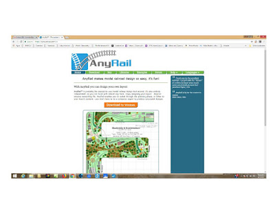
Here is a screen capture of the AnyRail website.


AnyRail website


As you can see, you can produce a really nice layout that includes the track and structures/objects from libraries of manufacturers products. Now that we have our layout pretty well planned I'm going to start exploring some of the features to help plan our scenery. You can also look at layouts in 3D...here is another screen dump from their website.


3D view of a sample Layout from AnyRail


Here is the 'final' design of our layout.

Current design of our layout


There is a logging camp area, sawmill area, town area and switching yard area. We also have a small farming area if space permits. The left leg is about 8 feet long and the top leg is about 14 feet long.

AnyRail is very easy to use. As you can see in the image, you can define your layout bench shape and use that as a background. You can setup various settings to define things like layout size, grid spacing, alerts for minimum radius curves, snap to grid and snap to track endpoints, auto-connect, etc. You can see this in this image.
Setting Options along the top Ribbon

Then you can select track part libraries from various manufactures to use to build your layout. It is basically drag and drop. Once you've selected an object, like a piece of flex track, you can change it's shape using various menu selections. In the case of a flex track you can define it's length if straight, or curve length and radius if it is a curve or easement. You can move it, rotate it and move it next to another piece of track and have them connect together.

Menu Options for Piece of Atlas #500 Flex Track


One of the best features, and the most frustrating, is the alert when you create a curve that is less than the minimum curve radius you set in the settings. When creating a curve and trying to have it meet up with another piece of track coming from another direction you want them to meet up and connect together. It can become very frustrating to have them very close but when they auto-connect one piece has to change shape a little so that it connects squarely into the other track piece. In the image the track marked with a red line shows that the minimum radius of that part of the track has fallen below 18” which is my minimum radius setting. What's a little 6” radius curve among friends.


Red Highlight for Tight Curve


The feature we are playing with now is the capability to set a track section height and then the slope 
of adjoining track to go up to and back down from that height. For example, you can set a piece of track to be a bridge at four inches high and then compute a 3 percent slope in each direction. This will help us determine the heights we can achieve for the track heights in the logging area around the mountains we have planned. Here is an example.


Heights and Slopes


The final feature I'll mention is that you can create various sections within your layout. Our layout has four major sections....the outer track, the switching yard, the reverse loop in the logging area and the reverse loop in the town area. This will help in our DCC wiring planning.


Track Sections Highlighted in Different Colors

Now that our benchwork is pretty complete we need to transfer our track plan to the benchtop. We are going to use the cookie cutter approach to track layout. AnyRail can print a full size printout. When I did the print dialog box said 208 pages!! Luckily it went down to 97 when I clicked on the suppress blank page option!


One page of 97 to Print


Next step....tape all those pages together!


Tuesday, May 29, 2018

Getting started...a lot to think about and learn!


In getting started with planning our layout I was a little overwhelmed with the variety of topics that I needed to know more about. I enjoyed doing scenery construction with my kids 25 years ago and the basic approach for that hasn't really changed much over the years but the whole electronics area is completely different. The whole change from DC (Direct Current) to DCC (Digital Command Control) is mind-boggling! In addition to scenery and electronics there is locomotives, mobile and stationary decoders, coupler types, layout operations and design, etc, etc, etc, etc!!

In my former life, before retirement, I was a research scientist for the federal government. I decided that the best way to approach my current situation was to collect some information and begin to research each of these topical areas. My next few blog entries will be about how I approached some of these areas, starting with putting together a design for our layout.

Some of Norm's and my earlier posts mentioned the criteria for our layout. I knew in the back of my mind that I wanted a woodworking theme which meant logging area, sawmill, lumber storage and I needed to combine this with making it fun for the grandchildren to run the trains. This meant a track where they could just continuously run a train without stopping plus areas where they could move a train and hook-up and/or decouple cars. I also wanted a lot of interesting scenery that they could help build.

I visited a couple of hobby stores and looked at the track layout books but I just didn't want to copy a track plan out of a book. I also wasn't really interested in any one particular real-life (prototype) railroad to emulate. Therefore, I started to browse the internet looking at layouts that other people had done with an eye towards specific components – logging, sawmills, ponds/rivers, continuous loops, reverse loops, mountains, sidings and yards for switching. I ended up printing over 20 layouts that I used as a guide for sketching out an initial design.


I knew that the space in my workshop was going to be in a corner so looking for L-shaped designs helped to reduce and focus my research. There are many online resources which include the Model Railroader Magazine website track layout database, Google search images, Pinterest, Model Railroad Academy among others. By moving cabinets and clamp storage racks around in my woodworking shop my plan was to make the L-shape with one leg about 8 feet and the other leg about 10 feet long. Given these constraints I came up with a 'first draft' drawing.


My next post will address starting with this drawing and converting it into something tangible using a software program called AnyRail.

Monday, May 28, 2018

The Plan for the the NF & CR Ry. Layout

Our concept for the layout, as Jeff said, is to combine the ability for continuously running "through" freight trains with local switching action in the yard, in town, in a logging camp and a sawmill area.  To that end, and within the constraint of available space, we designed a layout plan that we feel will reach these general goals.  Adjustments will be needed as we actually lay track.  The town area will undoubtedly get some industry-serving sidings and the logging area may undergo some adjustments.  But this plan outlines the needed benchwork and will serve as the basic plan for the layout.

Norm

The plan for the NF & CR Ry.  Red dots indicating reversing loop points.  Grid squares are 3 inches.

Why a train layout?!


     Why a train layout?!

     A few months ago my wife, Ellen, and I were commenting that when our kids were the same age as our grandchildren we had a model train layout in our basement.  As our kids grew older the trains and layout structures were packed away and grew dusty.  Maybe it was now time to get everything out again and put together a layout for their children....our grandchildren.  We had taken them to see 'Thomas the Train' and that was also one of their favorite TV shows.  Aiden is now 7 years old and his older brother, Anthony, is now 10 years old.

     I am a 'semi-professional' woodworker and have a 1000 sq. ft. shop so I have the space to dedicate a corner to a new layout.  We thought about having a layout in the house but with eight cats it would never survive!  I also have a very good friend, Norm Reid, that is very interested in model trains and also had train layouts as he was growing up.  Norm also shares my passion for woodworking and we are also avid photographers.  I asked Norm to help and he jumped at the idea!!

     One of the first things that I did was sit down and make a list of Goals and Drivers for the layout.  I knew this was going to be a large undertaking so I wanted something to help guide our initial planning.  I thought I would post the goals and drivers as my first entry into our new blog.

     Norm and I are both excited about creating a blog and take our followers along on this journey.  Through pictures you'll meet Norm, Aiden and Anthony, and I expect I'll end up in a few shots as well.  The text will give you our thoughts on the layout as we move from one stage to another.

     We all hope to have a good time...which is all that really matters.

Jeff


HO Model Train Goals and Objectives

Goals

  • Layout for grandchildren to run trains
  • Grandchildren can help with scenery construction
  • Build realistic scenery for photography close-ups
  • Woodworking theme
  • Not based upon prototype railroad but enough operational realism to keep it interesting
  • Share the experience with my friend Norm


Drivers for layout design

Electrical
  • Automatic reversing loops to change train direction
  • Powered turnouts with toggle switch control for grandkids
  • Multiple throttle controls for multiple operators
  • Run multiple locomotives/trains at one time
  • Signals/crossing gates at road intersections in town
  • As much animation (sound and operations) as possible
    • Switch activated controls for grandkids


Scenery

  • Logging area
  • Sawmill area
  • Town area
    • workshop
    • Burning house/building
      • firetruck with siren
      • house with lights & smoke
    • roads with crossing gates
  • Lake/river
  • Wood Trestle bridge
  • Tunnel with brick/stone facade
  • multiple levels of grading so layout is not flat
  • Photographic realistic landscape and structures


Operations

  • Steam engine era
    • Locomotives should have both sound and smoke
  • Ability to locate rolling stock around layout and in a yard and then build trains
  • Traverse from logging area to sawmill to workshop in town
  • Run multiple trains
  • Have route that can run continuously while industry areas are active with other trains