Showing posts with label building a layout. Show all posts

Wednesday, January 23, 2019

We've Started the Scenery

It's been a while since we posted anything, mainly due to the holidays.  But we've been working on the railroad and have continued to make progress.  First off, we've now gotten all of the Tortoise switch control boxes installed.  There are 19 in all, grouped into three zones.  We also have two of the zones--the logging area and the town area--temporarily wired, so we can throw the turnouts using the NCE controller.  The yard area is not yet wired and the seven turnouts there remain in waiting.

Next up for the turnouts is to build control panels.  Our plan is to insert printed plans of the layout behind thin acrylic sheets and mount the assembly on a hardboard sheet for stability.  We will then install push buttons to control the turnouts.  Red and green lights will indicate which way the turnout has been thrown.  We will have three panels in different locations convenient for operation in the logging, town and yard areas.

The biggest news is that we have now begun building scenery on the layout.  We began with the hillside where the logging camp, forest and farming area will reside.  Several structures will go into this area--the logging camp buildings and facilities, a barn and farm-related items--but a lot of the area will be open forest with lots of trees. 

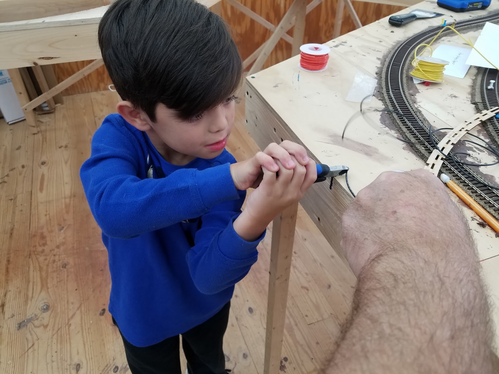
Jeff's grandsons Anthony and Aiden participated in the scenery-building.  We first laid strips of cardboard we ripped to about 1 1/2" wide on the table saw, creating a lattice.  We attached these to the plywood track base with staples and hot glue.  A word of advice: don't get the hot glue on your fingers; it will cause 2nd degree burns.  Don't ask us how we know.
With the lattice work woven into place, Jeff is stapling the joints to give the structure greater stability.
Once the lattice work was in place, we dipped plaster cloth, the kind used to make casts, in water and draped them over the cardboard, smoothing them down to fully engage the plaster and leave as seamless a surface as we could.  The boys did all the messy work of laying down and smoothing the plaster strips and had a ball doing so.  After the first round of plaster cloth set up, we put on a second layer.  When fully set up, this created a hard shell on which we can continue adding scenery.
Anthony (left) and Aiden apply the plaster cloth and smooth it down to get a seamless result.  This is messy work.  The boys loved it!
Our next job is to paint the plaster with latex paint--PPG Tobacco Brown--and then coat the area with Lou Sassi's "ground goop."  Once that base has been applied, we'll fully detail the area with trees, grasses, and the like.
The finished project, with two layers of plaster cloth.  We'll smooth this out with Plaster of Paris, then paint it Tobacco Brown and apply "ground goop" before proceeding to detail the area.  This is where the logging camp and farming area will reside.

We reported earlier that we are now running trains.  We have the "outer loop" pretty much debugged and track problems corrected, but the "inner loop" has a number of issues yet to be addressed.  We're happy to report, though that we've tested the reversing loops and the electronics seem to be working as intended.  We've tested the track with several locomotives.  Most are still set for the default cab number of 003.  We will soon reprogram them to their locomotive numbers so we can run multiple trains at once, something we've not yet tried.

So, while we've made a lot of progress in building the North Fork & Crooked Run Railway, there are still a lot of opportunities and challenges left for us to take on.  Stay tuned for updates.

Wednesday, November 14, 2018

Working on the electronics

Norm, Aiden and I were back working on the layout this week.  Norm finished up laying track and I helped Aiden drill holes for feeder wires.

drilling 1/8" hole for feeder wire

Aiden cut wire into 12" lengths for the feeder wires.  We made a mark on the bench where 12" was so that he could stretch the wire and then cut it.  


Measuring off 12" length of wire

cutting it to length


Once we had the wires cut Aiden pushed them through the holes.  He was just the right height to see the holes from the top and the bottom of the layout.

stringing wire from the top
and pushing them up from the bottom.  He also pulled them down from the top once in the hole.


Finally, a little playtime and getting a ground view of the layout!!  Aiden is a character!!


Wednesday, August 8, 2018

Readying the Layout for Track

In our most recent work session, we finished laying down the cork roadbed.  Then we sanded it to assure that it was level and free of bumps and any extruded silicone sealant.  We started sanding by hand with a 220 grit block, but found that to be hard going.  So we put a finishing sander to work with 180 grit paper installed.
Sanding the roadbed with the finishing sander was just the trick!
 Once the roadbed was sanded, it was ready for installing track.  We laid out the turnouts in their intended positions, then beginning at an arbitrary point on the layout, began to install track.
The layout with turnouts positioned at their intended locations
We drilled holes in each piece of track and all turnouts to allow nails to be driven through without splitting the rails.  Then we started the process of fitting the rail sections to the turnouts.  We were able to get track laid around about a third of the "outer loop."  We staggered the rails in each section by about four inches so there would be no kinks on the curves.

We've got a long way to go to get the rails fully installed.  We'll pick it up again when we're able to get together for another work session.

Thursday, August 2, 2018

More Roadbed!

As we explained in a previous post, we're using cork for the roadbed, gluing it to the plywood base with brown silicone sealant.  We had traced the planned rail locations using a pounce, or dressmaker's wheel, and then darkened the lines made by the pounce with a marking pen.  Following that, we inserted push pins at the mid-point of the lines, spacing them about every six inches or so.

The yard section of the layout, with push pins marking the centerpoint of the intended rail lines.
Then we laid out the cork against the push pins, cutting it to shape where needed to fit the turnouts.  We pinned the cork into final location to ensure that we had everything cut to fit the way we wanted it. 

A section of cork cut and pinned into location, ready for gluing.  This section will become the logging camp when the layout is finished.
Then, we lifted the cork sections and spread silicone sealant generously in the spot where the roadbed was to lie.  We pressed the roadbed back into position against the pins marking the center of the rail lines and, again using push pins, tacked the roadbed firmly down to the plywood base.

The main line and a passing track with the roadbed glued and pinned into position.
Because the silicone sealant is messy and because it was often easier to smooth it into place by hand, we wore gloves. 

The "hill" section of the layout, with all cork glued into position.  Note the test section of track pinned into position in the foreground.
Neatness didn't count here.  The fact that the silicone was spread around the plywood won't matter once we add scenery later.  We intentionally chose the brown sealant so any of it showing through the seams in the cork would not detract from the earthy appearance of the roadbed.

We laid one section of rail to test our planned method for joining sections on curves.  Since most of our layout is curves, this is especially important for us.  The method we'll be using is to stagger the joints in the rails by about six inches so no two rail ends appear side-by-side.  Although this is somewhat non-traditional, we feel it will make it much easier to avoid kinks in the rail at the point where joins occur.  Our test proved us right.  The fit of the rails when joined by our method was perfect and should lead to no derailments at those points.

The yard section with cork trimmed to fit and pinned into location, ready for gluing to the plywood base.
 In our latest session, we managed to get all the cork fit into final position and glued all of it except the yard portions.  We'll finish those in our next session and then start laying rail.  We're pleased with our progress and excited to see the bare bones of the benchwork taking the shape of an actual railroad layout.


Wednesday, July 25, 2018

Coal Tipple is done!!


     The Coal Tipple that I have been working on the past few weeks is finally done!  Aiden and I weathered the roof last week using white and light tan chalk.  We added the metal smokestack and applied a rust color to give it an aged, weathered look.  Then we added a rust wash along the roof to simulate rust slowly running down and off the roof.

     The past few days I've applied a diluted India ink wash to the sides of the building.  There is a little more added under the windows to simulate extra weathering from rain running down from the window sills.

     Finally, I painted and weathered the accessories that came with the kit.  This includes truck tires, a wooden barrel, a trash can and a wooden handled broom.  There were also a variety of posters/signs that that came with the kit.  I picked a few and weathered them using some light tan watercolor paint to make the white background paper look old.  I was really amazed by how much realism these accessories added to the tipple.  It really made the whole scene pop!

     Here are a few pictures of the final product:


Sunday, July 8, 2018

Securing the Subroadbed

In our most recent work session, we fastened down the subroadbed--1/2 inch plywood cut out to shape--so it is secure.  We installed risers to do the job.  The riser were made of scrap 1X3 inch lumber with a 1X1 inch rail fastened to the top for added support.  The riser rails were attached to the risers with wood glue and nails.  The risers were then screwed to the 1X4 benchwork at the correct height and the subroadbed screwed into the risers.

The risers were fabricated from scrap 1X3" lumber with a horizontal rail attached for added support

The subroadbed was secured to the risers with drywall screws
We completed the job of attaching all the subroadbed to the benchwork.

Aiden and Jeff securing the subroadbed to the benchwork

The elevated section of the layout.  Aiden is helping Jeff drill holes for screws to hold the subroadbed securely in position

We then made some conforming cuts in the plywood base to accommodate a planned gorge and river bed.
Aiden is cutting off a a projection from the end of what will be the logging camp portion of the layout
Even after carefully planning the elevation of the subroadbed, we discovered some places where the superelevation lay in the wrong direction or was higher than wanted.  We loosened the screws holding the risers in place and adjusted them to level them properly.

A check of the level showed the logging camp area to be out of level; we adjusted the lean of the riser to correct it
We are satisfied that we now have the benchwork in place, ready for laying track.  In our next session, we'll be laying cork roadbed and preparing to install track.  So we're getting closer to running trains!  It's getting exciting!

Norm

Friday, June 15, 2018

Making the Elevated Track Sections

Our latest work session, which was a long day of working, was to lay out the track locations on the plywood base and then cut the plywood in the "hill" section of the layout so we can elevate the track.

Here we are, ready for a work session in Jeff's shop; that's Norm on the left, Jeff on the right


We began by positioning the full scale pages on the plywood base until we got them into final position.

OK, so we had a little help getting the patterns into position on the plywood base
 The next task was to transfer the pattern to the plywood underneath.  To do this, we used a dressmaker's pattern tool called a pounce.  A pounce is a wheeled device with sharp spokes that poke through the pattern to the material underneath, in this case the plywood.

A dressmaker's pounce, also sometimes used to simulate rivets and nail holes in scale models
The recommended practice was to trace the pounce marks with a Sharpie, which was supposed to bleed through the holes left by the pounce and leave a trail on the plywood.  This, we found, was only partially successful, and we ended up re-tracing the pounce marks with marking pens so we would have lines we could follow when cutting out the plywood.

Here Norm is tracing the pounce wheel marks with a Sharpie; while some of the ink flowed through the holes, it did not leave the expected clear line for the saw to follow
We retraced the pounce marks, often better visible by the dents left in the plywood, so we would have clear lines to follow when we cut out the patterns with the jig saw
Next, we propped the plywood on 2X4s so we could cut out the patterns with a jig saw.

Jeff is cutting along the cut lines that mark the edge of the roadbed sections; in all cases we also marked the planned centerline for the track itself so that remains visible on the roadbed
Once we had the plywood cut, we clamped it into position at varying heights to plan the elevations we want to have for the final layout.  This is a critical phase, since it affects the rate of elevation and the difficulty trains will have climbing the ascents.  So, we only temporarily clamped the plywood into place to give ourselves plenty of time to think about things before we finalize them.

The layout with the plywood cut to shape for the roadbed and clamped into rough position to simulate elevations.  The plywood bent smoothly without kinks and it looks like this method will be successful in making a smooth-operating layout


Sunday, June 10, 2018

The Grandkids do some work and run some trains!

Just a quick update.....the grandkids, Anthony and Aiden were visiting today and got to help out on the benchwork.  Aiden (age 7) drilled the pilot holes while Anthony (age 10) put the screws in.  They really enjoyed getting on top of the bench and helping out!

My wife Ellen had a surprise for them.  She bought each of them an engineer's cap and red neckerchief!!  They even had their names on them..."Aiden" and "Tito" (Anthony in Spanish)  Of course, they had to wear the neckerchiefs around their faces like bandits!

After doing some work I put out a few straight pieces of track and let them have some fun running a couple of trains!!

Here are a few pictures that captured the fun we had today!!

Getting ready to work

Aiden would drill the pilot holes and Anthony would put the screw in

Aiden looking cute!

You can probably tell who is the clown in the family!!

Anthony went to town and had a good time

He loves to work in the shop

We even got underneath and drilled a few holes for future wires

running some trains

Aiden's turn

They are ready to run trains!!


Using Templates to Plan the Track Locations

The AnyRail program we used to plan the location for the Atlas FlexTrack we'll be using lets you print out full size patterns for the track and turnouts from the plan you've developed.  Jeff, who designed the layout using AnyRail, printed out 97 pages of full size layout patterns!  Our next task, which we undertook yesterday, was to piece together all those sheets and tape them so they would remain in place.  It was a job that took several hours to accomplish.  But, we can now see in realistic size just where the track will be placed and whether we want to make any adjustments to track location before we start laying roadbed and track.

Jeff is piecing together the pages for the yard
The yard completed, it's on to the loops serving the "town" area of the layout
A portion of the "town" area, showing the passing track that will allow mainline trains to bypass local freight trains
A view of the whole layout, with the yard in the foreground
What will be a mountainous area, with logging camp, elevated outer loop and a tunnel (indicated by the solid blocks); the log pond and sawmill are at the right rear
The completed "town" area, with the mountainous area in the background
For now, the patterns are laid out in their approximate final locations.  We still need to screw down the plywood so it's fully secure--we only tacked it in a few places so it wouldn't more around while we were testing the track locations.  Once that's finished, we'll position the patterns in their final locations.  Then we'll use a pounce--like seamstresses use to make patterns on cloth--to trace the centerline of the track.  And we'll use an awl to mark the location of the turnout throws so we can drill the holes for the Tortoise machines with accuracy.  That will then let us lay down the cork roadbed and prepare to lay track.

Sure, we could have done all this by the seat of our pants, drawing the lines for the track directly on the plywood base.  But by using AnyRail, we took our planning through several iterations until we had all the features we wanted and fit everything into the space we've got.  The printouts are merely the culmination of that process and they are carrying us a very long way toward our ultimate goal--getting track down so we can run some trains!

Friday, June 8, 2018

AnyRail...a software tool to build a layout


At the end of my last entry I said I would discuss the modeling tool that I used to design our layout. I had an initial pencil sketch that was derived from looking at other layouts and then combined with the physical constraints of the space I had available in my workshop. However, I needed a way to formalize the drawing into something that could be implemented.

After looking at the various software programs available online I decided on a program called AnyRail. There were numerous tutorials on Youtube to help get started, it appeared to have a large library of track components from a variety of companies and it was free...well almost. There is a free version which lets you use up to 50 track pieces in a design. Surprisingly, this worked out quite well until we decided to add the switching yard which put me over the 50 piece limit. I could have split the layout into sections and kept them in different files but in the end I decided to purchase the program. You can do some interesting things with the program, like set track heights and compute slope percentages and it just seemed easier to do if I had the complete layout in one file. So....I paid the $60 for a license. It seemed a little steep but I think it was worth the cost.

Here is a screen capture of the AnyRail website.


AnyRail website


As you can see, you can produce a really nice layout that includes the track and structures/objects from libraries of manufacturers products. Now that we have our layout pretty well planned I'm going to start exploring some of the features to help plan our scenery. You can also look at layouts in 3D...here is another screen dump from their website.


3D view of a sample Layout from AnyRail


Here is the 'final' design of our layout.

Current design of our layout


There is a logging camp area, sawmill area, town area and switching yard area. We also have a small farming area if space permits. The left leg is about 8 feet long and the top leg is about 14 feet long.

AnyRail is very easy to use. As you can see in the image, you can define your layout bench shape and use that as a background. You can setup various settings to define things like layout size, grid spacing, alerts for minimum radius curves, snap to grid and snap to track endpoints, auto-connect, etc. You can see this in this image.
Setting Options along the top Ribbon

Then you can select track part libraries from various manufactures to use to build your layout. It is basically drag and drop. Once you've selected an object, like a piece of flex track, you can change it's shape using various menu selections. In the case of a flex track you can define it's length if straight, or curve length and radius if it is a curve or easement. You can move it, rotate it and move it next to another piece of track and have them connect together.

Menu Options for Piece of Atlas #500 Flex Track


One of the best features, and the most frustrating, is the alert when you create a curve that is less than the minimum curve radius you set in the settings. When creating a curve and trying to have it meet up with another piece of track coming from another direction you want them to meet up and connect together. It can become very frustrating to have them very close but when they auto-connect one piece has to change shape a little so that it connects squarely into the other track piece. In the image the track marked with a red line shows that the minimum radius of that part of the track has fallen below 18” which is my minimum radius setting. What's a little 6” radius curve among friends.


Red Highlight for Tight Curve


The feature we are playing with now is the capability to set a track section height and then the slope 
of adjoining track to go up to and back down from that height. For example, you can set a piece of track to be a bridge at four inches high and then compute a 3 percent slope in each direction. This will help us determine the heights we can achieve for the track heights in the logging area around the mountains we have planned. Here is an example.


Heights and Slopes


The final feature I'll mention is that you can create various sections within your layout. Our layout has four major sections....the outer track, the switching yard, the reverse loop in the logging area and the reverse loop in the town area. This will help in our DCC wiring planning.


Track Sections Highlighted in Different Colors

Now that our benchwork is pretty complete we need to transfer our track plan to the benchtop. We are going to use the cookie cutter approach to track layout. AnyRail can print a full size printout. When I did the print dialog box said 208 pages!! Luckily it went down to 97 when I clicked on the suppress blank page option!


One page of 97 to Print


Next step....tape all those pages together!