Wednesday, December 5, 2018

We are running trains!!

December 1st was a big milestone for the North Fork & Crooked Run Railroad....we ran our first train around the logging area outer loop.  This was the first run of a train on our layout!!

Here it is!


We've tested the logging area outer loop, the logging area itself and the track around the city area.  Each area was tested independently since the control electronics have not been setup yet.  We have all the electronics mounted on a shelf and will install that this coming week.  Once the electronics are installed we will test the circuit breakers and reverse loop controllers.

We are excited to have trains running!!

Wednesday, November 14, 2018

Working on the electronics

Norm, Aiden and I were back working on the layout this week.  Norm finished up laying track and I helped Aiden drill holes for feeder wires.

drilling 1/8" hole for feeder wire

Aiden cut wire into 12" lengths for the feeder wires.  We made a mark on the bench where 12" was so that he could stretch the wire and then cut it.  


Measuring off 12" length of wire

cutting it to length


Once we had the wires cut Aiden pushed them through the holes.  He was just the right height to see the holes from the top and the bottom of the layout.

stringing wire from the top
and pushing them up from the bottom.  He also pulled them down from the top once in the hole.


Finally, a little playtime and getting a ground view of the layout!!  Aiden is a character!!


Sunday, October 7, 2018

Back from vacation and back to work

     Norm and his wife Betsy and my wife Ellen and myself went on a three week vacation to the New England states and into Canada.  We toured the Baseball Hall of Fame in Cooperstown, NY and visited the King Arthur Flour company (and store) outside Burlington, VT.  Both Norm and I like to bake so we enjoyed walking around and buying a lot at the company store!  From there we went up into Canada and visited Montreal, Quebec City, Prince Edward Island and Nova Scotia.  The highlight, in my opinion, was seeing low tide at Fundy Bay.  They have a daily 50 foot tide swing each day and we were able to walk on the ocean floor during low tide.  After Canada we drove along the coast of Maine and visited some lighthouses and finally stopped in Lancaster, PA on our way home.  It was a long trip but everyone had a good time and a favorite place to see.

     Now that we are back it is time to get back to the train layout.  On the trip I started a new FOS Scale Model called 'Tower Gas'.  I stained the walls and did some initial painting.  The final weathering will be done once the walls are all glued together.

     My grandson Aiden is visiting this weekend so he helped paint some of the parts.

Aiden helping to paint a small roof part


He takes this work very seriously!!


I glued the lower level walls together this morning.  I'm using a metal square to make sure all the corners are square.  This was an issue with my last model so I want to make sure everything lines up correctly this time.

The back wall and left side are glued and set in the background.  The front and right side are being glued using the square for alignment.


Here is the current state of the model.  The four lower level walls are glued together and the three walls for the upper level steeple are glued in place.  The fourth wall for the steeple will go on once the roof is in place.


More to come on this build.....


Sunday, August 12, 2018

Aiden wires the layout

Just a quick post to say that we've started to wire the layout and Aiden was a big help.  Norm was working on track bed and laying cork so Aiden helped me install some bus wires.

We first measured how much of each bus-wire was needed and cut it too length.  We are using 14 gauge wire for the bus wires.  Norm pitched in and held one end and Aiden used a drill to twist the wires together.  A lot easier than twisting the pairs of wires by hand!!

Aiden used a drill to quickly and easily twist wires together


Once we had a bus pair of wires twisted together, Aiden crawled under the layout (he could almost stand!) and put the wires in the plastic clips that we had screwed to the bottom of the layout.


Aiden could almost stand under the layout!


He was a big help because I would have to have crawled under the layout on my hands and knees!


Putting the wires into plastic clips

We have started to lay track so future posts will focus on the track work and installing feeder wires onto the track sections and connecting them to these bus wires.

Wednesday, August 8, 2018

Readying the Layout for Track

In our most recent work session, we finished laying down the cork roadbed.  Then we sanded it to assure that it was level and free of bumps and any extruded silicone sealant.  We started sanding by hand with a 220 grit block, but found that to be hard going.  So we put a finishing sander to work with 180 grit paper installed.
Sanding the roadbed with the finishing sander was just the trick!
 Once the roadbed was sanded, it was ready for installing track.  We laid out the turnouts in their intended positions, then beginning at an arbitrary point on the layout, began to install track.
The layout with turnouts positioned at their intended locations
We drilled holes in each piece of track and all turnouts to allow nails to be driven through without splitting the rails.  Then we started the process of fitting the rail sections to the turnouts.  We were able to get track laid around about a third of the "outer loop."  We staggered the rails in each section by about four inches so there would be no kinks on the curves.

We've got a long way to go to get the rails fully installed.  We'll pick it up again when we're able to get together for another work session.

Thursday, August 2, 2018

More Roadbed!

As we explained in a previous post, we're using cork for the roadbed, gluing it to the plywood base with brown silicone sealant.  We had traced the planned rail locations using a pounce, or dressmaker's wheel, and then darkened the lines made by the pounce with a marking pen.  Following that, we inserted push pins at the mid-point of the lines, spacing them about every six inches or so.

The yard section of the layout, with push pins marking the centerpoint of the intended rail lines.
Then we laid out the cork against the push pins, cutting it to shape where needed to fit the turnouts.  We pinned the cork into final location to ensure that we had everything cut to fit the way we wanted it. 

A section of cork cut and pinned into location, ready for gluing.  This section will become the logging camp when the layout is finished.
Then, we lifted the cork sections and spread silicone sealant generously in the spot where the roadbed was to lie.  We pressed the roadbed back into position against the pins marking the center of the rail lines and, again using push pins, tacked the roadbed firmly down to the plywood base.

The main line and a passing track with the roadbed glued and pinned into position.
Because the silicone sealant is messy and because it was often easier to smooth it into place by hand, we wore gloves. 

The "hill" section of the layout, with all cork glued into position.  Note the test section of track pinned into position in the foreground.
Neatness didn't count here.  The fact that the silicone was spread around the plywood won't matter once we add scenery later.  We intentionally chose the brown sealant so any of it showing through the seams in the cork would not detract from the earthy appearance of the roadbed.

We laid one section of rail to test our planned method for joining sections on curves.  Since most of our layout is curves, this is especially important for us.  The method we'll be using is to stagger the joints in the rails by about six inches so no two rail ends appear side-by-side.  Although this is somewhat non-traditional, we feel it will make it much easier to avoid kinks in the rail at the point where joins occur.  Our test proved us right.  The fit of the rails when joined by our method was perfect and should lead to no derailments at those points.

The yard section with cork trimmed to fit and pinned into location, ready for gluing to the plywood base.
 In our latest session, we managed to get all the cork fit into final position and glued all of it except the yard portions.  We'll finish those in our next session and then start laying rail.  We're pleased with our progress and excited to see the bare bones of the benchwork taking the shape of an actual railroad layout.


Wednesday, July 25, 2018

Coal Tipple is done!!


     The Coal Tipple that I have been working on the past few weeks is finally done!  Aiden and I weathered the roof last week using white and light tan chalk.  We added the metal smokestack and applied a rust color to give it an aged, weathered look.  Then we added a rust wash along the roof to simulate rust slowly running down and off the roof.

     The past few days I've applied a diluted India ink wash to the sides of the building.  There is a little more added under the windows to simulate extra weathering from rain running down from the window sills.

     Finally, I painted and weathered the accessories that came with the kit.  This includes truck tires, a wooden barrel, a trash can and a wooden handled broom.  There were also a variety of posters/signs that that came with the kit.  I picked a few and weathered them using some light tan watercolor paint to make the white background paper look old.  I was really amazed by how much realism these accessories added to the tipple.  It really made the whole scene pop!

     Here are a few pictures of the final product:


Wednesday, July 18, 2018

We're laying roadbed!!

A new phase of the NF & CR Ry. has begun....we are laying roadbed!!  The benchwork is complete and we have moved on to putting cork roadbed down.  It was exciting to actually start to see the roadbed start to take form.  We had experimented with running some trains up the grades and around the curves by just taping some track to the plywood but pretty soon we will start to lay track as well!


Norm putting adhesive caulk down onto the plywood.


We are using an adhesive caulk to glue the cork to the plywood base.  Norm spread the caulk with a putty knife following the centerlines that we had previously drawn.  Since the caulk would cover up the lines, we put push-pins along the centerline.  This also helped in placing the cork...we were able to just press the cork against the pins to follow the centerlines.


The caulk was easy to spread...but a little messy!


Once the cork was down, we used additional push-pins to keep the cork in place.  It was a little messy but it all went together well.  Next time....we will wear gloves!!


The cork went down onto the caulk and was pushed up to the pins.  Additional pins were used to held the cork in place.


Aiden even got into the fun and helped nail down a few push-pins.  He is having fun helping with the layout but I think he really would be happier running some trains!!


The supervisor even nailed some pins down!


Finally, some pictures of the roadbed at the end of the day.  We are doing the outer-loop first so that we can lay some track and run some trains.  It will be both exciting and amazing to watch that first train make a loop around the layout!!


Cork roadbed going around the outer loop


Close-up of the roadbed.

Sunday, July 8, 2018

Finished up the coal tipple roof

Aiden and I finished weathering the coal tipple roof.  We used some light tan and white pastel chalks to age the tar paper and then used a rust wash to add rust to the metal chimney pipe.  We also used the rust wash to show some on the rust washing down to the front edge of the roof.

Aiden adding some chalk to the roof


the weathered roof


  After we had fun working on the structure I had to put Aiden to work cleaning my shop.  He actually loves pushing the broom around and using the vacuum!!

Vacuuming my lathe


getting all the wood shavings off the floor


Securing the Subroadbed

In our most recent work session, we fastened down the subroadbed--1/2 inch plywood cut out to shape--so it is secure.  We installed risers to do the job.  The riser were made of scrap 1X3 inch lumber with a 1X1 inch rail fastened to the top for added support.  The riser rails were attached to the risers with wood glue and nails.  The risers were then screwed to the 1X4 benchwork at the correct height and the subroadbed screwed into the risers.

The risers were fabricated from scrap 1X3" lumber with a horizontal rail attached for added support

The subroadbed was secured to the risers with drywall screws
We completed the job of attaching all the subroadbed to the benchwork.

Aiden and Jeff securing the subroadbed to the benchwork

The elevated section of the layout.  Aiden is helping Jeff drill holes for screws to hold the subroadbed securely in position

We then made some conforming cuts in the plywood base to accommodate a planned gorge and river bed.
Aiden is cutting off a a projection from the end of what will be the logging camp portion of the layout
Even after carefully planning the elevation of the subroadbed, we discovered some places where the superelevation lay in the wrong direction or was higher than wanted.  We loosened the screws holding the risers in place and adjusted them to level them properly.

A check of the level showed the logging camp area to be out of level; we adjusted the lean of the riser to correct it
We are satisfied that we now have the benchwork in place, ready for laying track.  In our next session, we'll be laying cork roadbed and preparing to install track.  So we're getting closer to running trains!  It's getting exciting!

Norm

Converting a Brass Locomotive to DCC

I have a love of steam locomotives and it's perhaps natural that his interest should gravitate to brass engines.  I like the details and weight of brass locomotives and also look forward to the challenge of restoring them to excellent running condition and converting them to DCC and sound.  Inspired by an article in Railroad Model Hobbyist on installing replacement motors and gearing, I decided that making such conversions is probably within my ability, even though I've never done one before.

I located a suitable subject for conversion on eBay: a Pacific Fast Mail Tenshodo USRA 0-8-0 that he would like to see operating in the yard of the North Fork & Crooked Run Railway.  This engine was unpainted and the electrical connections to the motor were severed.  The coal load, which had been added to the original model, was partially missing.
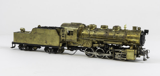
The PFM Tenshodo USRA 0-8-0 in its original condition
The first task was to build a cradle to hold the locomotive, and others to follow, upside down for disassembly and repair.  I had some surplus walnut left over from another project and, using pocket hole screws, made a U-shaped device 15 inches long.  To the sides of the U, I stapled a piece of cloth draped into the well of the U so it would hold a locomotive at a height convenient for working that would safely protect the locomotive's details.

Then I tested the conductivity of the locomotive with an ohmmeter.  The drivers proved to be insulated, an essential criterion.  Had they not been insulated, the whole project would have had to be scrapped, as replacing the drivers would have been out of the question.  I got good conductivity from the drawbar to the motor wire, on the other hand.  However, this was not really important, as the motor is slated for replacement.

The next step was to remove the boiler and tender shell.  The boiler is held in place by a large screw through the steam chests and two small screws located at the back of the cab.  Four screws hold the tender shell to its frame.  I removed the tender wheels at the same time.  I had purchased a plastic box with dividers to hold the parts from the locomotive, and as I removed these, I placed them in individual compartments with a label to remind me what they are.

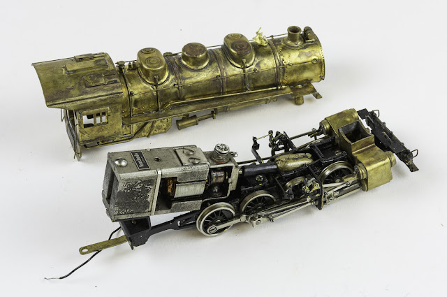
The disassembled USRA 0-8-0


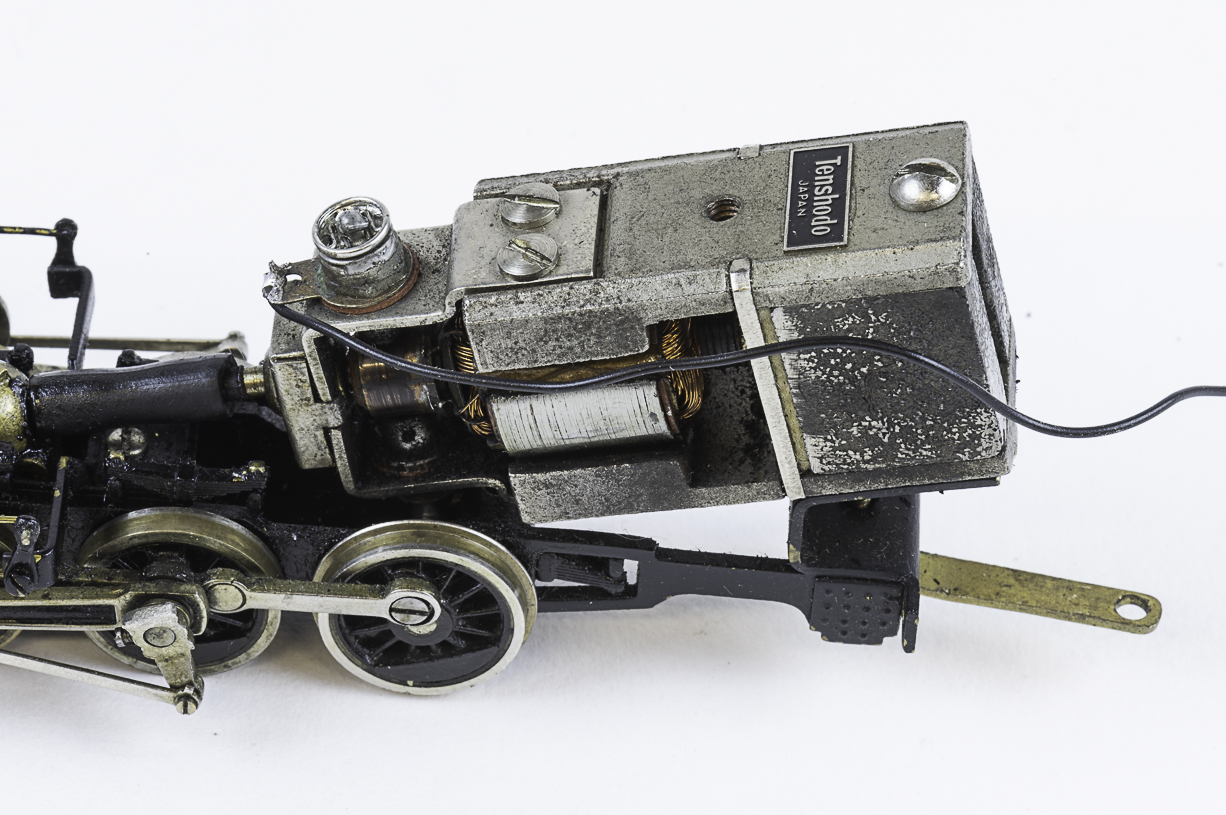
I then evaluated the motor's ability to power the disassembled drive train.  It operated only haltingly and then only when I put hand pressure on it.  Clearly, it was a candidate for replacement.  The original motor was an open frame type.  Experts in this field call for replacing these originals with can motors.

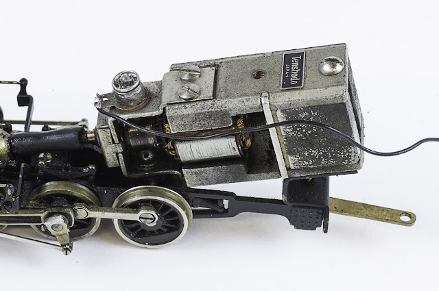
The original open frame Tenshodo motor failed to function and clearly needed replacing
The gearbox was also found to have a lot of slop in it and I decided it too needed replacing, as did the coupling mechanism.  These imported brass locomotives used a piece of rubber tubing to join the motor to the gearbox.  The tubing had enough flexibility to accommodate movement in the gears during starting and stopping movements.  But over time, they stiffen up and can even crack, thus losing their ability to transmit power to the wheels.  The recommended practice is to replace this linkage with a dogbone style coupling.

The original gearbox had a lot of play in it and it and the coupling mechanism were clear candidates for replacement
I then measured the interior size of the boiler and tender to determine the sizes of parts that could be fit into them and ordered parts for upgrading and restoring the locomotive.  Based on the measurements and my own intentions for the restored model, I ordered the following parts:

From Osorail, the following North West Short Line parts:

  • A 36:1 idler gearbox with ball bearings; this will make the switcher run a little more slowly than the 28:1 gearbox, and the ball bearings will help it run more smoothly
  • A 16mm flywheel
  • The 2032D-9 flat can motor
  • Axle stock and shaft universal connectors
I also ordered some tools to help ensure accurate and precise installation of parts:
  • The Sensipress to press together wheels and gears
  • The Quarterer, to assure that the drive wheels are properly quartered
  • The Aligner for 3mm axles to enable precise wheel and fear alignment
I probably would not have purchased these tools for a single locomotive, but I have in mind converting others in the future and it made sense to have them available for the first conversion to help it go smoothly and accurately.

From Yankee Dabbler, via eBay:
  • The Soundtraxx Tsunami2 TSU-2200 2 amp sound card for steam engines which contains a large variety of steam locomotive and whistle sounds, among other effects, and which incorporates DCC capability so a separate DCC card is not required
  • The Soundtraxx Current Keeper, which contains a capacitor to keep power to the locomotive even when it's passing over dirty track with poor conductivity
From Tony's Trains:
  • A TDS high bass 28mm speaker
  • A TDS speaker enclosure
While waiting for these parts to arrive--and the time to install them--I cleaned and painted the locomotive and tender.  I'll address that in a future posting.

Norm

Wednesday, July 4, 2018

Building a Coal Tipple with Aiden

In my initial post I mentioned that I had a layout with my son's over 25 years ago.  Well, I had started to build a Coal Tipple back then but only got about 25% done before the boys had lost interest in trains and everything was packed up.  I had packed this structure away and whenever we moved or cleaned up I saw the box and said to myself that someday I would finish it. 

Over the past few weeks I've been working on it and Aiden is visiting for a few days over July 4th holiday.  Today he helped make the roof.  We are using black construction paper for the base and will texture it and weather it.

Here is the coal tipple without the roof.


We cut the construction paper into strips that are scaled to real tar paper and then Aiden sanded one side with 220 sandpaper to simulate a rough texture.


After they were sanded we applied glue and put them onto a cardboard backing overlapping them as we moved from the bottom to the top.


Once both sides of the top were done Aiden put glue around the edge of the coal tipple's top and we placed the roof onto the top.


We now have a roof!!!   We then took an x-acto knife and picked up various portions of the paper to simulate the paper peeling up due to age and the weather.  The goal is to make the roof look aged.


Tomorrow's goal will be to add some chalks to the roof to continue to weather the top.  Will probably use some light browns and white. 

A little while after we finished, Aiden said to me..."I really enjoyed doing that with you".   Not a dry eye in the house!!!

Friday, June 15, 2018

Making the Elevated Track Sections

Our latest work session, which was a long day of working, was to lay out the track locations on the plywood base and then cut the plywood in the "hill" section of the layout so we can elevate the track.

Here we are, ready for a work session in Jeff's shop; that's Norm on the left, Jeff on the right


We began by positioning the full scale pages on the plywood base until we got them into final position.

OK, so we had a little help getting the patterns into position on the plywood base
 The next task was to transfer the pattern to the plywood underneath.  To do this, we used a dressmaker's pattern tool called a pounce.  A pounce is a wheeled device with sharp spokes that poke through the pattern to the material underneath, in this case the plywood.

A dressmaker's pounce, also sometimes used to simulate rivets and nail holes in scale models
The recommended practice was to trace the pounce marks with a Sharpie, which was supposed to bleed through the holes left by the pounce and leave a trail on the plywood.  This, we found, was only partially successful, and we ended up re-tracing the pounce marks with marking pens so we would have lines we could follow when cutting out the plywood.

Here Norm is tracing the pounce wheel marks with a Sharpie; while some of the ink flowed through the holes, it did not leave the expected clear line for the saw to follow
We retraced the pounce marks, often better visible by the dents left in the plywood, so we would have clear lines to follow when we cut out the patterns with the jig saw
Next, we propped the plywood on 2X4s so we could cut out the patterns with a jig saw.

Jeff is cutting along the cut lines that mark the edge of the roadbed sections; in all cases we also marked the planned centerline for the track itself so that remains visible on the roadbed
Once we had the plywood cut, we clamped it into position at varying heights to plan the elevations we want to have for the final layout.  This is a critical phase, since it affects the rate of elevation and the difficulty trains will have climbing the ascents.  So, we only temporarily clamped the plywood into place to give ourselves plenty of time to think about things before we finalize them.

The layout with the plywood cut to shape for the roadbed and clamped into rough position to simulate elevations.  The plywood bent smoothly without kinks and it looks like this method will be successful in making a smooth-operating layout